Services and applications that are affected by high load require technologies to address this issue. Network Load Balancing is a technology that allows system administrators to configure clusters that distribute traffic between several servers. Suppose you have a website that receives a large number of requests and cannot be handled by one server. In this case you would configure a NLB cluster to distribute traffic across multiple web servers and thus ensuring that the website can serve all requests.
In this article I will show you how to configure Network Load Balancing (NLB) within your Windows Server infrastructure. For this tutorial I will be using two virtual machines hosted in my VMWare testing environment.
let’s open up the Server Manager console and install the Network Load Balancing feature. Note that this feature must be installed on both servers. Click on Add roles and featuresbutton and skip all pages until you reach the Features section. From the features list select Network Load Balancing and proceed with the installation. Note that Powershell support for NLB will also be installed:
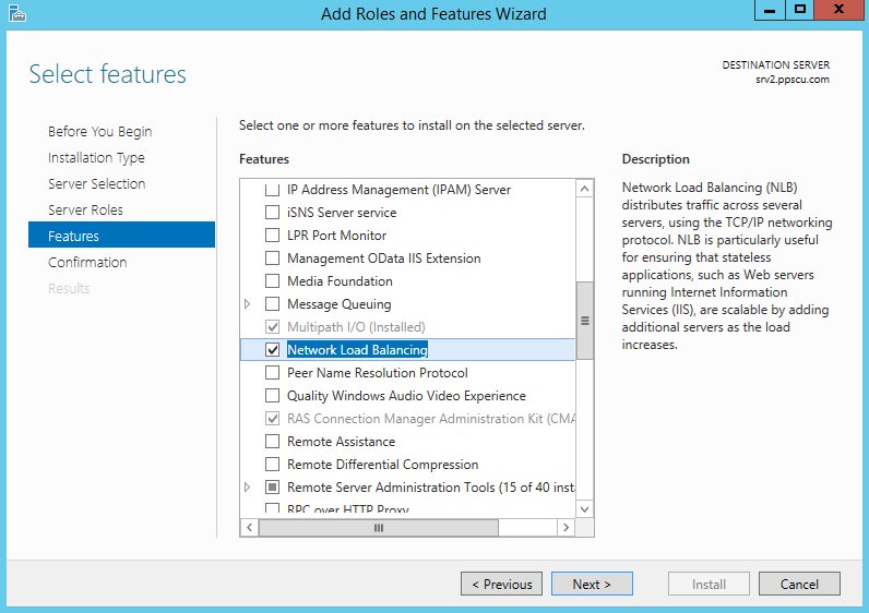
Once the install operation is completed, open the Network Load Balancing Managerconsole from Administrative Tools.
Within the NLB console, click on Cluster from the upper menu and select New. Now enter the local server IP address and click on Connect. Select one of the available network interfaces that will be part of the NLB process and proceed with the following section. I’ve added one of my two servers to the cluster, you will need to add the second machine afterwards.
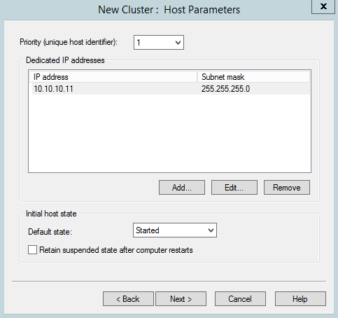
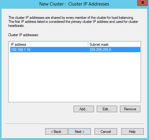
In the following section we’ll need to configure the priority of the specified server and the initial host state. Note that you can add multiple IP addresses for one host. Continue the wizard by pressing the Next button. We’ll need to assign an IP address for the load balancing cluster that is shared between all nodes. This IP address is not physically assigned to a network card and instead a virtual network adapter is created. Note that you can add multiple IPs for load balancing, but the first one will be considered the primary address. For testing purposes I will add a random IP address:
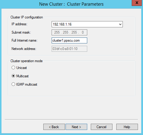
The next section is used to configure cluster parameters. Enter the cluster full internet name (in my example cluster1.ppscu.com) and the cluster’s operation mode. A NLB cluster must operate in one of the following modes:
Unicast – the MAC address of the cluster virtual network adapter is shared with all cluster nodes. If your servers have only one network adapter then the MAC address of the VNA replaces the MAC address of the physical interface. By using only one network adapter on each server, communication will be made only with devices that are part of the same subnet as the given node. It’s recommended that you use two network adapters for each node, one used for load balancing and the other one for server management.
Multicast – the server will retain its original MAC and IP address while also using the MAC and IP address of the cluster’s virtual network adapter. All devices from all subnets can communicate with the node, but multicasting is used for cluster communication.
IGMP Multicast – uses the IGMP protocol (Internet Group Management Protocol) to increase network performance by using multicast clients registered to a IGMP multicast server.
From the three available options, choose multicast and proceed with the next section:
From the port rules section we configure how traffic is managed on the NLB cluster. By specifying the designated port or port range you filter packets so that only desired traffic is received by the NLB cluster:
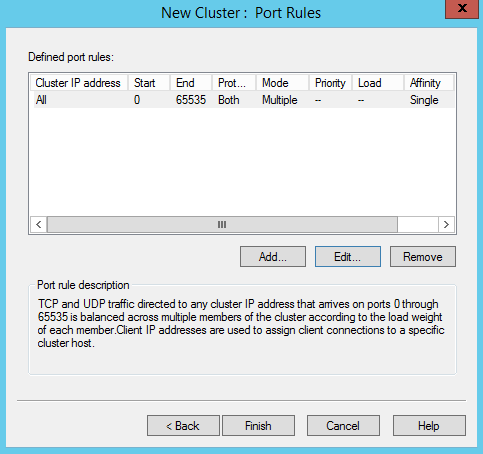
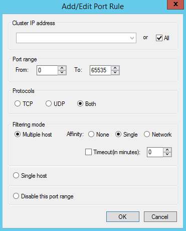
Rules can be created on each of the cluster’s IP address. By pressing the Edit button we configure the port range, protocol (TCP or UDP) and the filtering mode. There are three available filtering methods, as follows:
Multiple host – used to configure all nodes within the NLB cluster to respond to requests. The node’s affinity determines which of the cluster’s servers handles the traffic. There are three options available here:
· None – traffic is distributed between all cluster nodes
· Single – uses all nodes to handle NLB traffic, but a node will receive all traffic for a specific request. This is used when stateful connections are used and is the default option. The timeout parameter is configured to discard connections once a connection passes a certain period of time.
· Network – redirects client requests to the closest available node. Just like netmask ordering, requests are sent to the appropriate node based on the subnet of the client.
Single host – in this mode the traffic that matches a filtering rule will be handled by one node only.
Disable this port range – this mode is used to block the traffic sent on the specified ports.
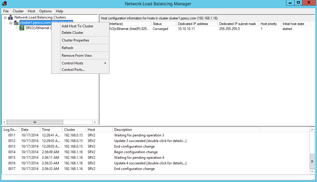
The newly created node will appear in the NLB Manager console. We will add the second server by right clicking the cluster and selecting Add Host to Cluster:
Now you will need to follow the same procedure as we did earlier for the first node. Once the wizard is completed, the second node will be added to the NLB cluster.
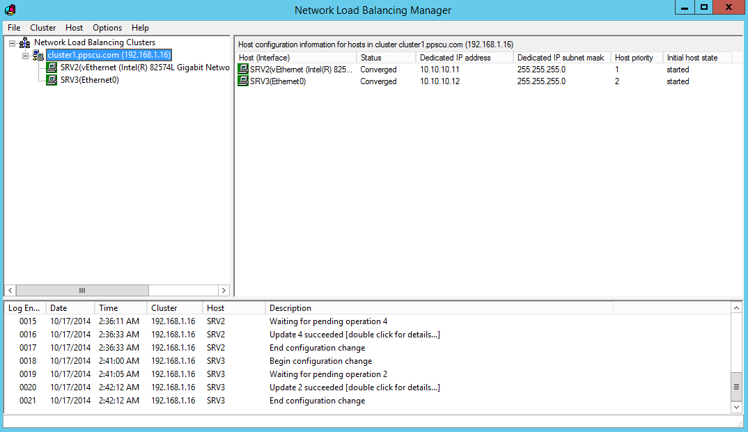
With this NLB cluster we can now distribute traffic destined for our applications between these two hosts. I’ve used this type of configuration when balancing traffic between two IIS servers. The port rules where handling only HTTP (port 80) and HTTPS (port 443) traffic. Most enterprises use dedicated network devices for load balancing such as Netscaler, Cisco Ace, etc, but it’s good to remember that Windows Server Editions can support this feature as well. Hope this article will serve you well in understanding how this technology works and how to install and configure NLB clusters.
